 |
| September 03, 2024 | Volume 20 Issue 33 |
Motion Control News & Products

Designfax weekly eMagazine

Archives
Partners
Manufacturing Center
Product Spotlight
Modern Applications News
Metalworking Ideas For
Today's Job Shops
Tooling and Production
Strategies for large
metalworking plants
Versatile Transport System: Turbocharge conveyance
![]() THK's Versatile Transport System is a high-mix production solution that will keep your production line moving. Its linear motor drive enables high-speed operations, and processing can be performed directly on top of the system's freely recirculating sliders. This highly precise, modular system has many unique features, including easily adjustable stop positions, flex layouts with path splitting and parallelization, and easy addition/subtraction of extension pieces.
THK's Versatile Transport System is a high-mix production solution that will keep your production line moving. Its linear motor drive enables high-speed operations, and processing can be performed directly on top of the system's freely recirculating sliders. This highly precise, modular system has many unique features, including easily adjustable stop positions, flex layouts with path splitting and parallelization, and easy addition/subtraction of extension pieces.
View the video.
Tech Tip: How to keep heavy loads balanced
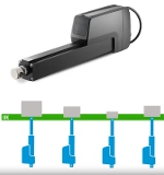 Some Thomson smart linear actuators have a position-based synchro-nization option to help manage unbalanced loads when using multiple units. The system adjusts the speed of each actuator to keep them starting, moving, and stopping synchronously, regardless of their respective load distribution. So useful. So smart.
Learn all about this feature.
Micropositioning stages ensure high accuracy
 PI now offers fast delivery of the L-511 linear microposi-tioning stage, which is designed for applications requiring minimum incremental motion down to 20 nm and drive forces up to 22 lb. The L-511 can be combined to form XY or XYZ motion systems and integrated with rotary stages for enhanced flexibility. Features high-load recirculating ball bearings for exceptional durability, even under demanding, repetitive cycles. To enhance positioning accuracy and automation throughput, this stage integrates non-contact, direction-sensing optical reference point switches located at mid-travel.
Learn more.
Robots think and act on the fly at moving assembly line speeds
 Inbolt and FANUC are launching a manufacturing breakthrough enabling FANUC robots to tackle one of the most complex automation challenges: performing production tasks on continuously moving parts at line speeds. With Inbolt's AI-powered 3D vision, manufacturers can now automate screw insertion, bolt rundown, glue application, and other high-precision tasks on parts moving down the line without costly infrastructure investments or cycle time compromises.
Learn more.
Best high-speed rotary bearing in THK history
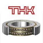 THK has developed its best-performing, high-speed rotary bearing ever: the High-Speed, Double-Row Angular Contact Ring BWH. This rotary bearing has balls aligned inside a cage between the inner and outer rings and is part of the THK Rotary Series, along with the cross-roller ring. The main features of this product are its ability to receive loads in all directions as well as its high rigidity and rotational accuracy, which are equal to that of cross-roller rings. By adopting a new structure to change the rolling elements from rollers to balls, this product achieves the greatest high-speed performance ever offered by THK.
Learn more.
Elevating tables: Precise vertical positioning in tight spaces
 As semicon-ductors and optical components become smaller and more sophisticated, the TZ Series of precision elevating tables from IKO International provides exceptional vertical positioning accuracy in a compact size. This unit features a unique wedge mechanism guided in the vertical direction by a pair of IKO C-Lube Super MX linear motion rolling guides arranged in parallel to achieve highly precise positioning with exceptional rigidity. An optional linear encoder provides full closed loop control to achieve positioning accuracy as high as 0.005 mm, with repeatability of +/-0.001 mm.
Learn more and get all the specs.
This cobot is all about safety around people
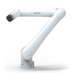 The COBOTTA PRO from DENSO Robotics is a lightweight, high-speed collaborative robot designed for communication between workers and robots while maximizing productivity. It delivers a blend of productivity and safety for both simple tasks and multi-step processes like assembly and inspection work. The 6-axis unit operates at speeds up to 2,500 mm per sec when no workers are near and slows or stops when people approach. Two models available: PRO 900 (max payload 6 kg) and PRO 1300 (max payload 12 kg). Many more functions and features.
Learn more.
Powerful, pull-type clapper solenoids handle myriad jobs
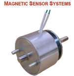 New powerful, low-profile, pull-type clapper solenoids are available from Magnetic Sensor Systems (MSS). Applications include valve control, locks, starters, ventilators, clamping, sorting, appliances, tools, HVAC, brakes, clutches, switches, mixing, fire suppression systems, door controls, detent latches, and more. The S-16-264 Series of 17 Pull-Type Clapper Solenoids have ampere turns (windings) adjusted to meet the specific force and duty cycle requirements of your application. They provide up to 130 lb (578 N) of force.
Get all the specs for these solenoids and other options.
Tech Tip: Belt, screw, or chain-driven actuator?
 Bishop-Wisecarver provides a quick, very useful guide to help you evaluate the right drive strategy for your system: belt, screw, or chain-driven actuator. Each drive type has unique advantages and limitations, so evaluating all your options will help you find the most suitable actuator setup for your specific application needs.
Read the Bishop-Wisecarver blog.
Ultra-precise linear stage -- down to 0.005 microns
 PI, a global leader in precision motion control and nanoposi-tioning, now offers fast delivery of the L-511 linear micropositioning stage, which is designed for applications requiring minimum incremental motion down to 20 nm, drive forces up to 22 lb, and multi-axis configuration options. The L-511 can be combined to form XY or XYZ motion systems and integrated with rotary stages. A variety of drive and encoder options (stepper and servo motors, rotary, and linear encoders) enable ultra-fine sensitivity. Applications include: metrology, laser processing, semiconductors, biotech, optical alignment, and advanced automation.
Learn more and get all the specs.
Choosing the right stepper motor: PM or hybrid?
 According to the experts at Lin Engineering, there are two primary types of stepper motors to consider: permanent magnet (PM) and hybrid. But which is right for your application? Both types have their advantages and disadvantages, and the choice ultimately depends on your specific requirements.
Read this informative Lin Engineering article.
New PTFE-free linear guide for precise positioning
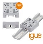 The new drylin WWP linear guide from igus features a PTFE-free locking carriage. Engineered from lubrication-free, high-performance polymers and aluminum, the guide offers a lightweight, hygienic, and low-maintenance alternative to complex mechanical and electronic adjustment systems. It is significantly more compact and lightweight than conventional recirculating ball-bearing systems. Applications include interior components in vehicles, aircraft, and furniture.
Learn more and get all the specs.
Heavy-duty gear units for mixing and agitating systems
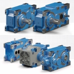 MAXXDRIVE industrial gear units from NORD DRIVE-SYSTEMS are an established drive solution for heavy-duty applications. In addition to conveying, lifting, and driving, they also play an important role in mixing and agitating systems. MAXXDRIVE units feature a compact, one-piece UNICASE housing that delivers long service life, easy maintenance, and quiet operation. Their robust design handles high axial and radial loads, achieves output torques up to 2,495,900 lb-in., and powers up to 8,075 hp.
Learn more.
What are non-captive linear actuators?
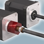 According to PBC Linear, their new non-captive linear actuators are different from the more common external versions of lead screw-driven linear actuators because they allow the lead screw to completely pass through the motor. This fundamental difference offers advantages for designs that have limited space available or for engineers looking to shrink the overall size of their design package.
Read the full PBC Linear blog.
Güdel introduces Swiss-quality tracks for cobots
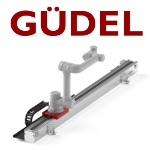 Güdel Inc. is highlighting new technologies at Automate 2025 booth #2418 that demonstrate its unmatched ability to solve automation engineering challenges. One is the Cobomover, a 7th-axis linear track purpose-built for collaborative and lightweight robots. Designed and manufactured in Switzerland, this unit extends the working range of robots up to 5 m, allowing them to operate multiple workstations and perform a variety of tasks without manual repositioning. Compatible with over 60 cobots and small traditional robots.
Learn more and get all the specs.
What's a unified momentum model? New theory could improve the design and operation of wind farms
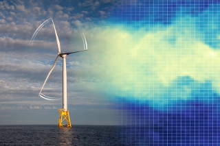
Engineers at MIT have developed a comprehensive model that accurately represents the airflow around rotors even under extreme conditions, such as when the blades are operating at high forces and speeds, or are angled in certain directions. [Credit: Image courtesy of the researchers]
The first comprehensive model of rotor aerodynamics could improve the way turbine blades and wind farms are designed and how wind turbines are controlled.
By David L. Chandler, MIT
The blades of propellers and wind turbines are designed based on aerodynamics principles that were first described mathematically more than a century ago. However, engineers have long realized that these formulas don't work in every situation. To compensate, they have added ad-hoc "correction factors" based on empirical observations.
Now, for the first time, engineers at MIT have developed a comprehensive, physics-based model that accurately represents the airflow around rotors even under extreme conditions, such as when the blades are operating at high forces and speeds, or are angled in certain directions. The model could improve the way rotors themselves are designed, but also the way wind farms are laid out and operated. The new findings are described in the journal Nature Communications, in an open-access paper by MIT postdoc Jaime Liew, doctoral student Kirby Heck, and Michael Howland, the Esther and Harold E. Edgerton Assistant Professor of Civil and Environmental Engineering.
"We've developed a new theory for the aerodynamics of rotors," Howland says. This theory can be used to determine the forces, flow velocities, and power of a rotor, whether that rotor is extracting energy from the airflow, as in a wind turbine, or applying energy to the flow, as in a ship or airplane propeller. "The theory works in both directions," he says.
Because the new understanding is a fundamental mathematical model, some of its implications could potentially be applied right away. For example, operators of wind farms must constantly adjust a variety of parameters, including the orientation of each turbine as well as its rotation speed and the angle of its blades, in order to maximize power output while maintaining safety margins. The new model can provide a simple, speedy way of optimizing those factors in real time.
"This is what we're so excited about, is that it has immediate and direct potential for impact across the value chain of wind power," Howland says.
Modeling the momentum
Known as momentum theory, the previous model of how rotors interact with their fluid environment -- air, water, or otherwise -- was initially developed late in the 19th century. With this theory, engineers can start with a given rotor design and configuration, and determine the maximum amount of power that can be derived from that rotor -- or, conversely, if it's a propeller, how much power is needed to generate a given amount of propulsive force.
Momentum theory equations "are the first thing you would read about in a wind energy textbook, and are the first thing that I talk about in my classes when I teach about wind power," Howland says. From that theory, physicist Albert Betz calculated in 1920 the maximum amount of energy that could theoretically be extracted from wind. Known as the Betz limit, this amount is 59.3% of the kinetic energy of the incoming wind.
Just a few years later, however, others found that the momentum theory broke down "in a pretty dramatic way" at higher forces that correspond to faster blade rotation speeds or different blade angles, Howland says. It fails to predict not only the amount, but even the direction of changes in thrust force at higher rotation speeds or different blade angles: Whereas the theory said the force should start going down above a certain rotation speed or blade angle, experiments show the opposite -- that the force continues to increase. "So, it's not just quantitatively wrong, it's qualitatively wrong," Howland says.
The theory also breaks down when there is any misalignment between the rotor and the airflow, which Howland says is "ubiquitous" on wind farms, where turbines are constantly adjusting to changes in wind directions. In fact, in an earlier paper in 2022, Howland and his team found that deliberately misaligning some turbines slightly relative to the incoming airflow within a wind farm significantly improves the overall power output of the wind farm by reducing wake disturbances to the downstream turbines.
In the past, when designing the profile of rotor blades, the layout of wind turbines in a farm, or the day-to-day operation of wind turbines, engineers have relied on ad-hoc adjustments added to the original mathematical formulas, based on some wind tunnel tests and experience with operating wind farms, but with no theoretical underpinnings.
Instead, to arrive at the new model, the team analyzed the interaction of airflow and turbines using detailed computational modeling of the aerodynamics. They found that, for example, the original model had assumed that a drop in air pressure immediately behind the rotor would rapidly return to normal ambient pressure just a short way downstream. However, it turns out, Howland says, that as the thrust force keeps increasing, "that assumption is increasingly inaccurate."
And the inaccuracy occurs very close to the point of the Betz limit that theoretically predicts the maximum performance of a turbine -- and therefore is just the desired operating regime for the turbines. "So, we have Betz's prediction of where we should operate turbines, and within 10 percent of that operational set point that we think maximizes power, the theory completely deteriorates and doesn't work," Howland says.
Through their modeling, the researchers also found a way to compensate for the original formula's reliance on a one-dimensional modeling that assumed the rotor was always precisely aligned with the airflow. To do so, they used fundamental equations that were developed to predict the lift of three-dimensional wings for aerospace applications.
The researchers derived their new model, which they call a unified momentum model, based on theoretical analysis, and then validated it using computational fluid dynamics modeling. In follow-up work not yet published, they are doing further validation using wind tunnel and field tests.
Fundamental understanding
One interesting outcome of the new formula is that it changes the calculation of the Betz limit, showing that it's possible to extract a bit more power than the original formula predicted. Although it's not a significant change -- on the order of a few percent -- "it's interesting that now we have a new theory, and the Betz limit that's been the rule of thumb for a hundred years is actually modified because of the new theory," Howland says, "and that's immediately useful." The new model shows how to maximize power from turbines that are misaligned with the airflow, which the Betz limit cannot account for.
The aspects related to controlling both individual turbines and arrays of turbines can be implemented without requiring any modifications to existing hardware in place within wind farms. In fact, this has already happened, based on earlier work from Howland and his collaborators two years ago that dealt with the wake interactions between turbines in a wind farm, and was based on the existing, empirically based formulas.
"This breakthrough is a natural extension of our previous work on optimizing utility-scale wind farms," he says, because in doing that analysis, they saw the shortcomings of the existing methods for analyzing the forces at work and predicting power produced by wind turbines. "Existing modeling using empiricism just wasn't getting the job done," he says.
In a wind farm, individual turbines will sap some of the energy available to neighboring turbines because of wake effects. Accurate wake modeling is important both for designing the layout of turbines in a wind farm, and also for the operation of that farm, determining moment to moment how to set the angles and speeds of each turbine in the array.
Until now, Howland says, even the operators of wind farms, the manufacturers, and the designers of the turbine blades had no way to predict how much the power output of a turbine would be affected by a given change such as its angle to the wind without using empirical corrections. "That's because there was no theory for it. So, that's what we worked on here. Our theory can directly tell you, without any empirical corrections, for the first time, how you should actually operate a wind turbine to maximize its power," he says.
Because the fluid flow regimes are similar, the model also applies to propellers, whether for aircraft or ships, and also for hydrokinetic turbines such as tidal or river turbines. Although they didn't focus on that aspect in this research, "it's in the theoretical modeling naturally," he says.
The new theory exists in the form of a set of mathematical formulas that a user could incorporate in their own software, or as an open-source software package that can be freely downloaded from GitHub. "It's an engineering model developed for fast-running tools for rapid prototyping and control and optimization," Howland says. "The goal of our modeling is to position the field of wind energy research to move more aggressively in the development of the wind capacity and reliability necessary to respond to climate change."
Published September 2024
Rate this article
View our terms of use and privacy policy